optical_physics (4)

Holographic Microscopy...

Figure

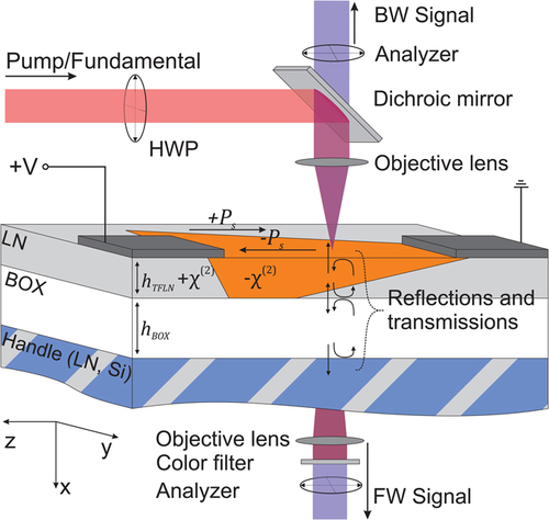
FIG. 1. (a) Schematic of an inline digital holographic microscope. In a typical setup, a collimated laser (light red) illuminates a sample, which scatters light (dark red wavefronts). The transmitted and scattered light passes through an objective and tube lens, which focuses the light onto a digital camera. (b) A hologram of a polystyrene particle obtained from an inline holographic microscope.

Topics: Holography, Optical Physics, Microscopy, Modern Physics

In the past few years, the venerable field of holographic microscopy has been revitalized by computational data analysis. It is now possible to fit a generative (forward) model of scattering directly to experimentally obtained holograms of complex microscopic objects. This approach enables precision measurements: it allows the motion of colloidal particles and biological organisms to be tracked with nanometer-scale precision and their optical properties to be inferred particle by particle. In this Perspective, we discuss how the model-based inference approach to holographic microscopy has opened up new applications. We also discuss how it must evolve to meet the needs of emerging applications that demand lower systematic uncertainties and higher precision. In this context, we present some new results on how modeling the optical train of the microscope can enable better measurements of the positions of spherical and nonspherical colloidal particles. Finally, we discuss how machine learning might play a role in future advances. Though we do not exhaustively catalog all the developments in this field, we show a few examples and some new results that spotlight open questions and opportunities.


Precise measurements in digital holographic microscopy by modeling the optical train, Ronald Alexander, Brian Leahy, Vinothan N. Manoharan, Journal of Applied Physics

Read more…

Blind Mice Seeing...

Figure

Topics: Bioengineering, Optical Physics, Nanorods, Nanotechnology

Even in the dark, rattlesnakes and their fellow pit vipers can strike accurately at small warm-blooded prey from a meter away. Those snakes, and a few others, can see in the IR—but not with their eyes. Rather, they have a pair of specialized sensory organs, called pit organs, located between their eyes and their nostrils and lined with nerve cells rich in temperature-sensitive proteins that cause the neurons to fire when heated.1 The pits work like pinhole cameras to focus incoming thermal radiation onto their heat-sensitive back walls; the thermal images are then superimposed with visual images in the snake’s brain.

Heat-responsive neurons are not unique to snakes. We have them over every inch of our skin, to feel objects warm to the touch, and on our tongues, to taste spicy food. But the snakes’ ability to resolve the source of radiated heat at a distance is unusual.

Inspired by the snakes, Dasha Nelidova and her colleagues at the Institute of Molecular and Clinical Ophthalmology in Basel, Switzerland, are developing a new treatment for forms of blindness caused by the degeneration of retinal photoreceptors.2 Using gene therapy, they endow remaining retinal cells with thermoresponsive proteins, thereby compensating for their lost light sensitivity with heat sensitivity. The proteins by themselves aren’t sensitive enough to rival normal vision, so the researchers tether them to gold nanorods, as shown in figure 1. The 80-nm-long nanorods strongly absorb near-IR light at 915 nm and convey the concentrated heat to the attached proteins.

Near-IR nanosensors help blind mice see, Johanna L. Miller, Physics Today

Read more…

Second Harmonic Microscopy...

1.5113727.figures.online.f1.jpg
Fig. 1 Typical geometry for the SH microscopy investigation of poled x-cut LNOI.


Topics: Applied Physics, Optical Physics, Thin Films


Abstract

Thin film lithium niobate has been of great interest recently, and an understanding of periodically poled thin films is crucial for both fundamental physics and device developments. Second-harmonic (SH) microscopy allows for the noninvasive visualization and analysis of ferroelectric domain structures and walls. While the technique is well understood in bulk lithium niobate, SH microscopy in thin films is largely influenced by interfacial reflections and resonant enhancements, which depend on film thicknesses and substrate materials. We present a comprehensive analysis of SH microscopy in x-cut lithium niobate thin films, based on a full three-dimensional focus calculation and accounting for interface reflections. We show that the dominant signal in backreflection originates from a copropagating phase-matched process observed through reflections, rather than direct detection of the counterpropagating signal as in bulk samples. We simulate the SH signatures of domain structures by a simple model of the domain wall as an extensionless transition from a −χ(2) to a +χ(2) region. This allows us to explain the main observation of domain structures in the thin-film geometry, and, in particular, we show that the SH signal from thin poled films allows to unambiguously distinguish areas, which are completely or only partly inverted in depth.


Second harmonic microscopy of poled x-cut thin film lithium niobate: Understanding the contrast mechanism
Journal of Applied Physics 126, 114105 (2019); https://doi.org/10.1063/1.5113727

Read more…

Lamina Tenuissima...

thinnest-optical-device-2.jpg
Illustration of a tungsten disulfide monolayer suspended in air and patterned with a square array of nanoholes. Upon laser excitation, the monolayer emits photoluminescence. A portion of this light couples into the monolayer and is guided along the material. At the nanohole array, periodic modulation in the refractive index causes a small portion of the light to decay out of the plane of the material, allowing the light to be observed as guided mode resonance. Courtesy: E Cubukcu, UCSD


Note: lamina tenuissima = thinnest (Latin)

Topics: Applied Physics, Nanotechnology, Optical Physics, Photonics


Researchers have succeeded in making the thinnest ever optical device in the form of a waveguide just three atomic layers thick. The device could lead to the development of higher density optoelectronic chips.

Optical waveguides are crucial components in data communication technologies but scaling them down to the nanoscale has proved to be no easy task, despite important advances in nano-optics and nanomaterials. Indeed, the thinnest waveguide used in commercial applications today is hundreds of nanometres thick and researchers are studying nanowire waveguides down to 50 nm in the laboratory.

“We have now pushed this limit down to just three atoms thick,” says Ertugrul Cubukcu of the University of California at San Diego, who led this new research effort. “Such a thin waveguide, which is at the ultimate limit for how thin an optical waveguide can be built, might potentially lead to a higher density of waveguides or optical elements on an optoelectronic chip – in the same way that ever smaller transistors have led to a higher density of these devices on an electronic chip.”

Cubukcu and colleagues’ waveguide is just six angstroms thick. This makes it 104 times thinner than a typical optical fiber and about 500 times thinner than on-chip optical waveguides in integrated photonic circuits.


Three-atom-thick optical waveguide is the thinnest ever, Belle Dumé, Physics World

Read more…